Graphical/Text Design Entry
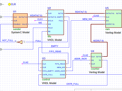
Schematic / Block Diagram Editor
The Block Diagram Editor is a tool for graphical entry of VHDL, Verilog and EDIF designs. If your HDL design is in large part structural, it may be easier for you to enter its description graphically as a block diagram, rather than writing the source code. The Block Diagram Editor will then convert the diagram automatically into structural VHDL, Verilog or EDIF netlist. With Active-HDL, you can mix both types of description. For example, the top-level design entity can be a block diagram while the components instantiated in it are described using HDL code/EDIF netlist and/or state diagrams.

Benefits of using schematic editor:
- The Schematic editor supports both bottom-up and top-down methodologies
- Schematic libraries for vendors allow you to create technology oriented block diagrams
- The Hierarchical property of editor helps you create multiple pages of the schematics for complex blocks
- Block diagram files can be translated to VHDL, Verilog or EDIF netlist
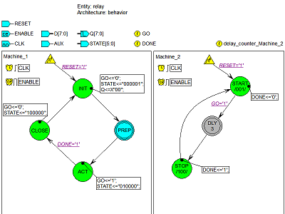
State Machine Editor
The State Diagram Editor is a tool designed for the graphical editing of state diagrams of synchronous and asynchronous machines. Drawing a state diagram is an alternative approach to the modeling of a sequential device. Instead of writing the HDL code by yourself, you can enter the description of a logic block as a graphical state diagram. The editor will then automatically generate the HDL code based on the entered graphical description. Due to the intuitive graphic form, state diagrams are easy-to-learn and far more readable than the HDL code.

Benefits of using State Machine Editor:
- It gives a visual map that specifies the flow, events and actions from state to state which is much easier to read and understand
- Built-in testbench generator can help verify your state machine very quickly
- It can be served as a great collaboration tool during design meetings as they are easy to understand and explain
- They can be used to document the design at various levels of abstraction
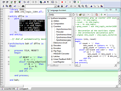
HDL Text Editor
The HDL Editor is a text editor designed for editing an HDL source code. It is tightly integrated with the compiler and simulator to enable debugging capabilities. Some of the major features of HDL text editor are Keyword highlighting (VHDL, Verilog/SystemVerilog, C/C++, SystemC, OVA, and PSL), Support for code groups and code structure, Auto-complete and Auto-format, Bookmarks and named bookmarks for easy navigation through source code, Breakpoints and Columns Selection.

Benefits of using HDL Text Editor:
- Cross probing between waveform viewer and HDL text editor makes debugging easier
- Signals can be add to waveform viewer directly from HDL Editor
- Supports live value probes in source code during simulation
- Language templates for VHDL, Verilog, SystemVerilog and SystemC to help write code quickly
Code2Graphics
The Code2Graphics converter is a tool designed for automatic translation of VHDL, Verilog/SystemVerilog and EDIF netlist into Active-HDL schematics and state diagrams. It analyzes VHDL, Verilog, or EDIF files and generates one or more schematic and state diagram files depending on the number of design entities, modules, or cells found in the analyzed file. The resulting schematics and state diagrams files can be automatically attached to a design or saved in a separate location.
Benefits of using Code2Graphics:
- It abstracts the information from a design and presents in a graphical way
- Design reuse process can be greatly enhanced by graphical visualization of RTL designs
- It helps creating the perfect documentation for the complex RTL design projects
Corporate Headquarters
2260 Corporate Circle
Henderson, NV 89074 USA
Tel: +1 702 990 4400
Fax: +1 702 990 4414
https://www.aldec.com
©2025 Aldec, Inc.
